Instrument Design
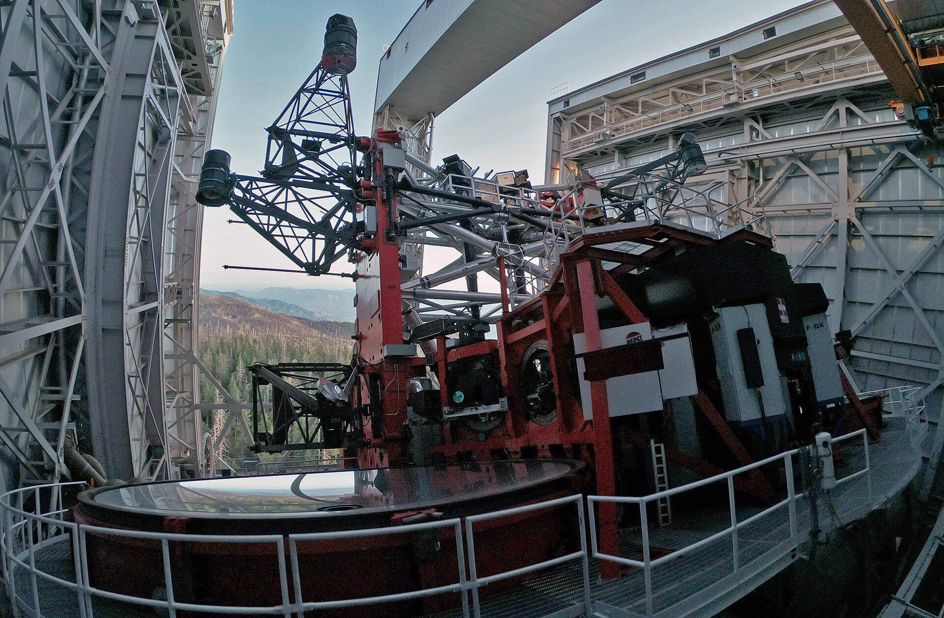
iLocater was designed starting from fundamental EPRV science requirements. Light is fed to the instrument by the Large Binocular Telescope (LBT) Adaptive Optics (AO) system (shown above), which uses the telescope adaptive secondary mirrors in combination with pyramid wavefront sensors in the Large Binocular Telescope Interferometer (LBTI). The beam from each 8.4m telescope primary is injected into separate single-mode fibers (SMFs) that illuminate the remotely located instrument spectrograph. The end-to-end iLocater instrument comprises four primary subsystems:
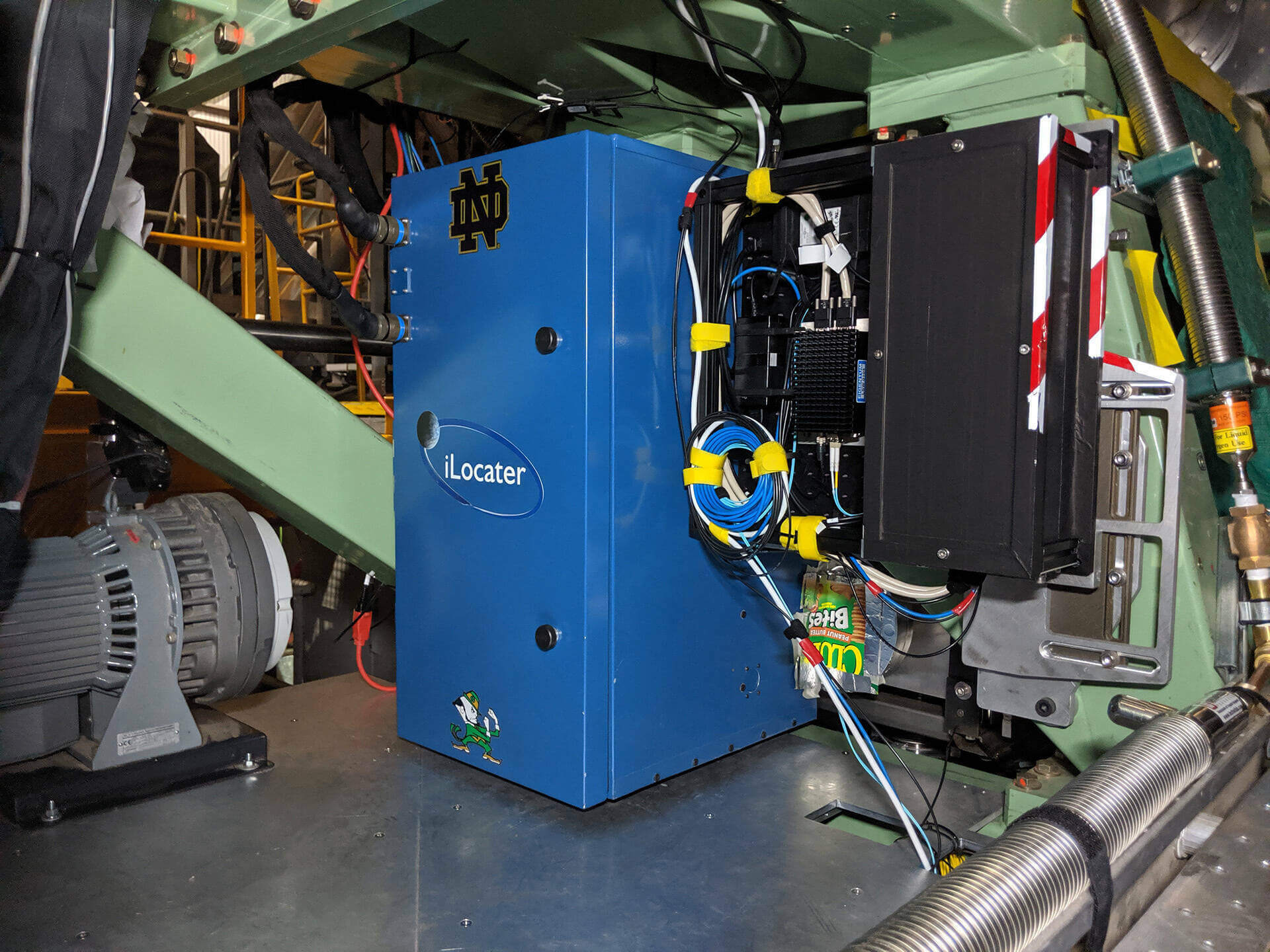
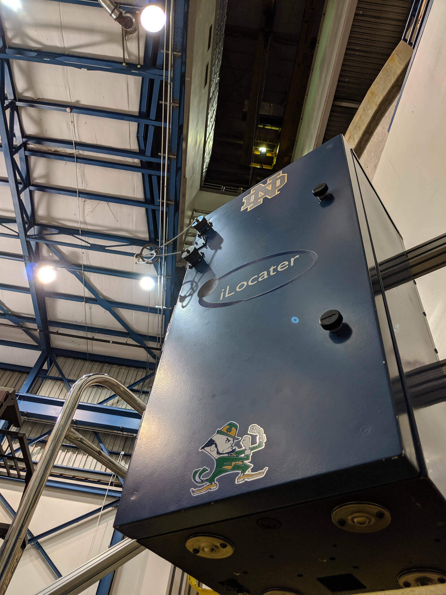
- A fiber injection system (acquisition camera) for each LBT primary mirror installed within the instrument bay of LBTI on the telescope instrument gallery. These systems couples AO-corrected starlight from one of the LBT primary mirrors into a single SMF.
- A high-resolution, cross-dispersed, echelle spectrograph fed by the SMFs from the fiber injection systems and imaged onto a Teledyne H4RG-10 detector.
- A cryostat to thermally stabilize the spectrograph in vacuum that is located away from the telescope enclosure in a vibrationally quiet environment.
- A wavelength calibration system (WCS) to provide a wavelength solution and stable Doppler reference for the spectrograph.
Instrument Specifications
| Instrument Property | Value |
|---|---|
| Spectral Wavelength: | 0.97-1.31μm (Y- and J-band) |
| Imaging Wavelength: | 0.90-0.95μm |
| Spectral Resolution: | R=132,000-273,000, Rmedian=190,000 |
| Spatial Resolution: | 40 milli-arcseconds |
| Detector (Spectrograph): | H4RG-10 |
| Detector (Imaging): | ANDOR Zyla CMOS |
| Fiber Type: | SM-980 |
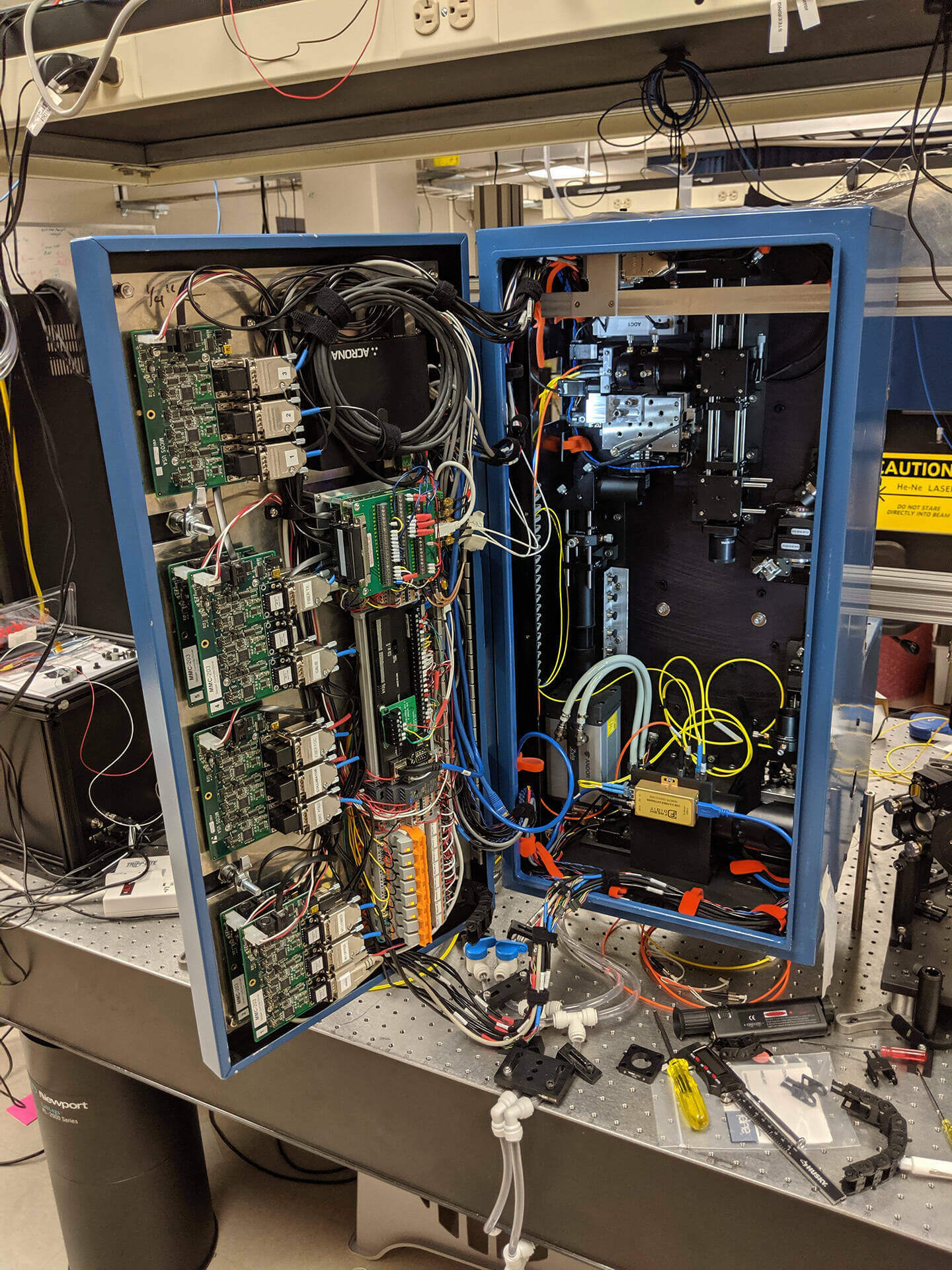
Acquisition Camera
Each iLocater acquisition camera is designed to couple AO-corrected starlight from one side of the LBT into an SMF. The system uses bright, on-axis science targets as their own natural guide star for AO correction. The acquisition camera optical design reformats the incident telescope beam (f/41.2 from LBTI) to the optimal profile for SMF injection using custom triplet lenses. The system includes elements for beam acquisition, beam steering, atmospheric dispersion correction, internal tip/tilt correction (to mitigate residual AO tip/tilt and the effects of telescope vibrations), imaging, and precision fiber positioning capabilities. Full details can be found in Crass et al. 2021.
The acquisition camera for the left (SX) primary of the telescope was installed and commissioned at the LBT in Summer 2019. On-sky fiber coupling efficiency of the SX system was quantified for a broad range of seeing conditions, zenith angles, stellar spectral types, and target magnitudes. Absolute coupling efficiency of 30% was achieved, exceeding the science requirement for iLocater.
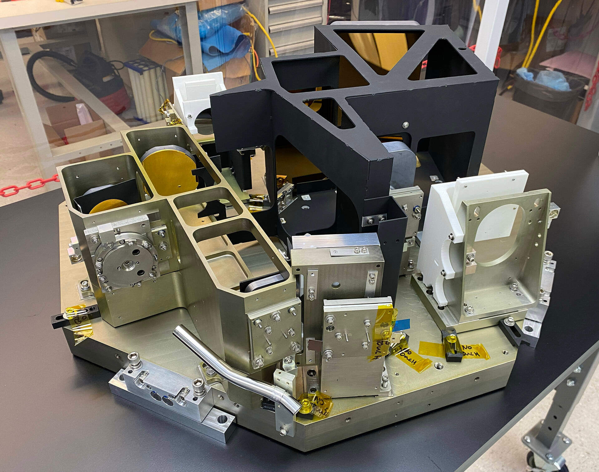
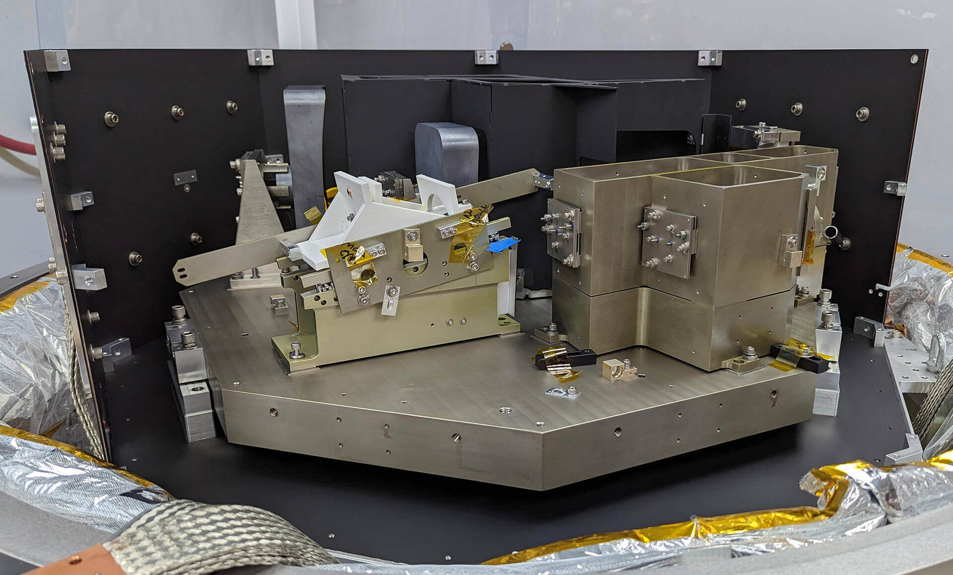
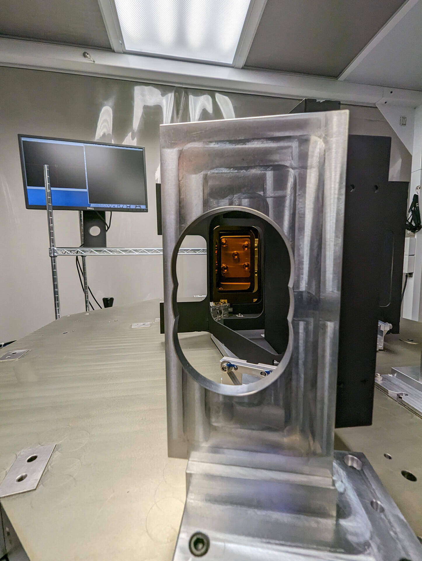
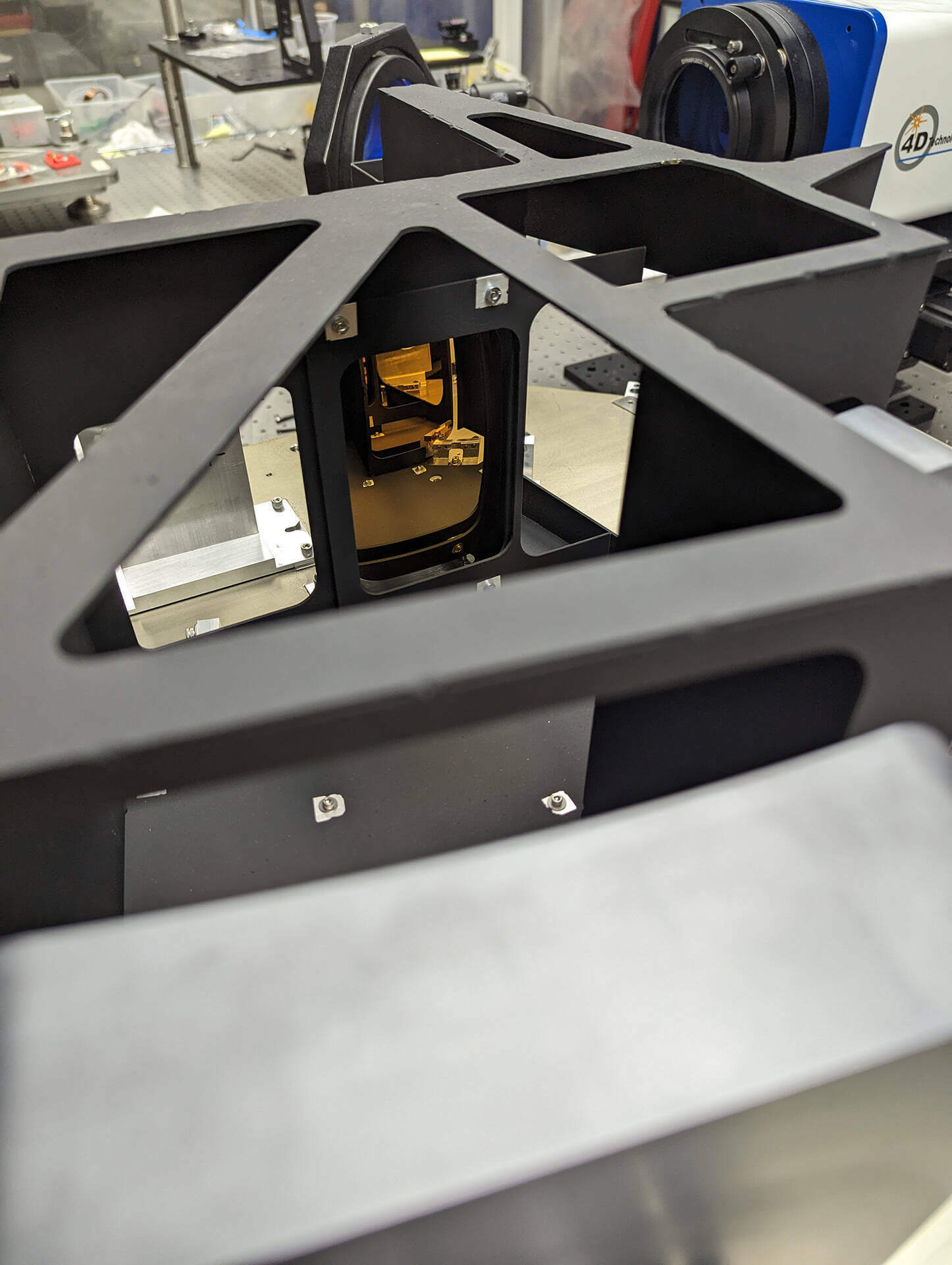
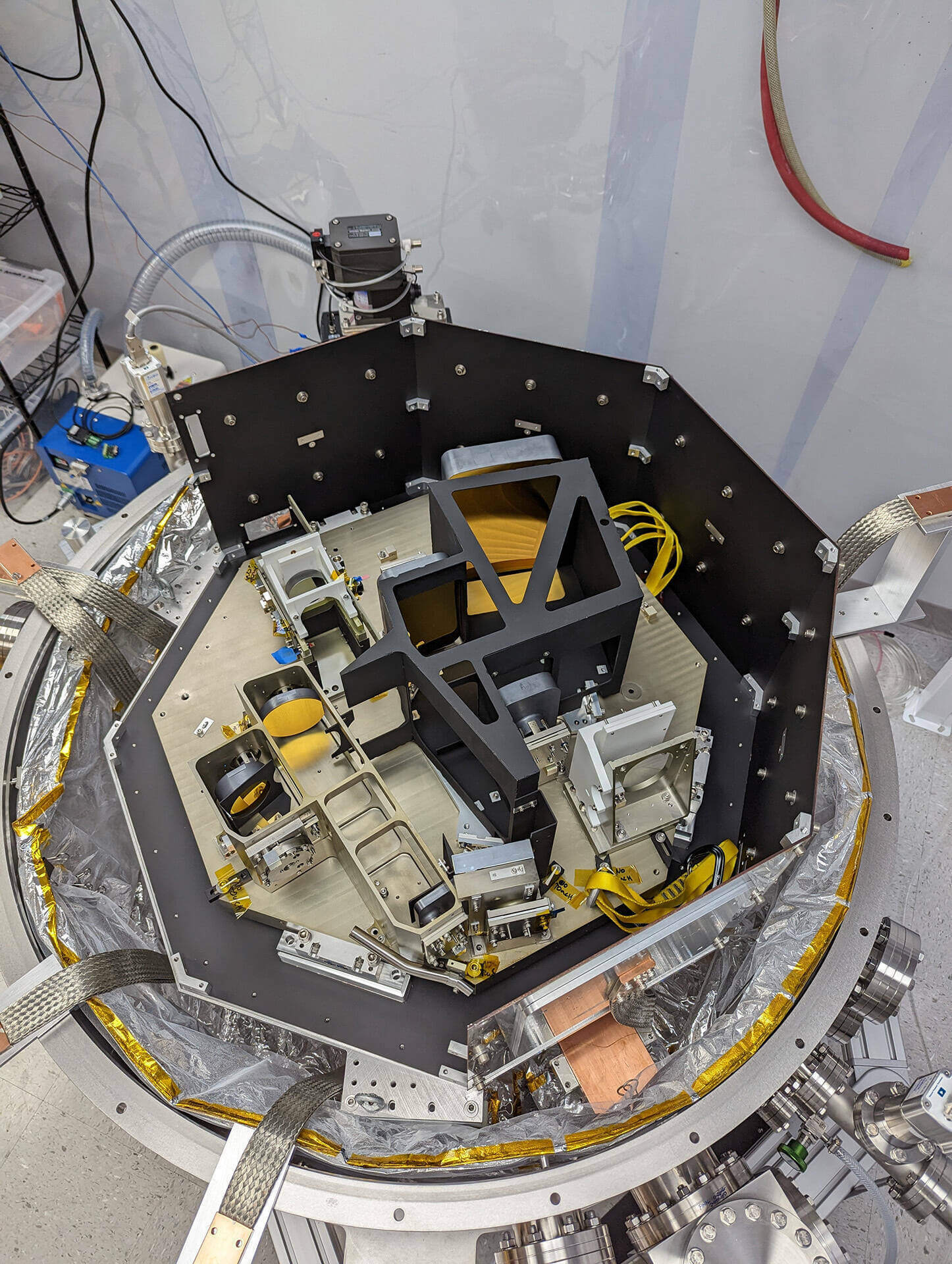
Spectrograph
The instrument spectrograph is a cross-dispersed echelle design that delivers high-resolution (R=132,000-273,000, Rmedian=190,000) NIR (λ=0.97-1.31μm) spectra with diffraction-limited performance. Three fibers illuminate the spectrograph: one fiber for each telescope primary mirror and a third fiber for simultaneous calibration. Light is dispersed by an R6 diffraction-grating (13.33 lines/mm) prior to cross-dispersion by a reflection grating (265 lines/mm). Full details can be found in Crass et al. 2022.
The spectrograph optomechanical system comprises two independent modules: a collimator that re-images the fiber input and illuminates the echelle grating, and a camera that refocuses the cross-dispersed beam onto an H4RG-10 detector from Teledyne. The NASA Roman Space Telescope program has made a Hawaii-4RG-10 (4096-pixel) array available to the iLocater project. The small pixel pitch of the detector (10μm) is well matched to the diffraction-limited input and provides 3.0 pixels per resolution element.
The spectrograph uses gold coated silicon optics combined with Invar optomechanics to provide an intrinsically stable, compact (675mm diameter) diffraction-limited system. At the instrument operating temperature (T=80-100K), this combination provides a well-matched CTE between materials allowing the system to behave as a single homogenous material. The instantaneous CTE value of silicon at this temperature (<0.35ppm/K) is an order of magnitude smaller than aluminum and provides stability comparable to Zerodur. The spectrograph optomechanical modules have low wavefront error (<λ/10 RMS at 633nm) ensuring a diffraction-limited spectrograph fabricated from stable materials.

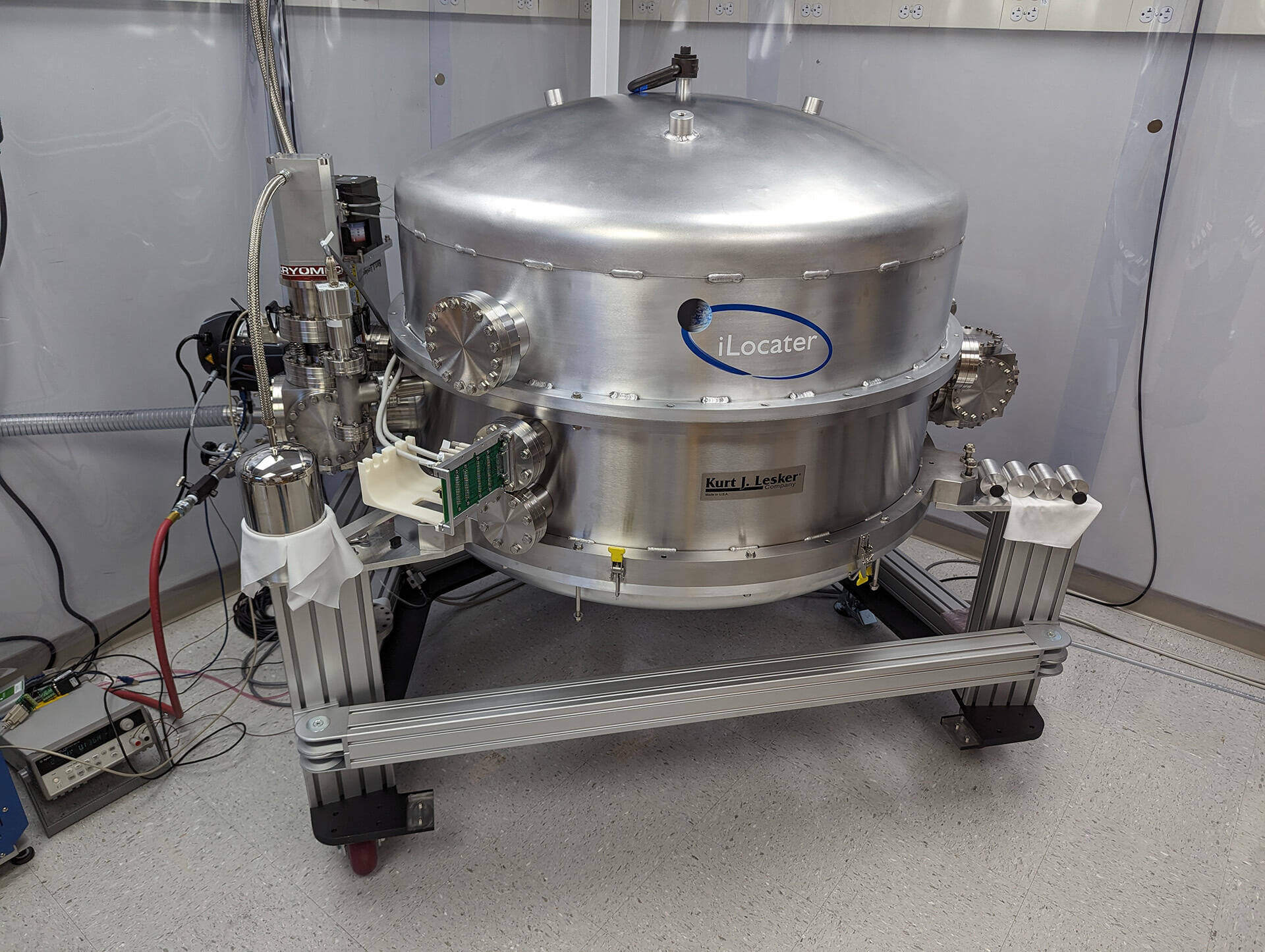
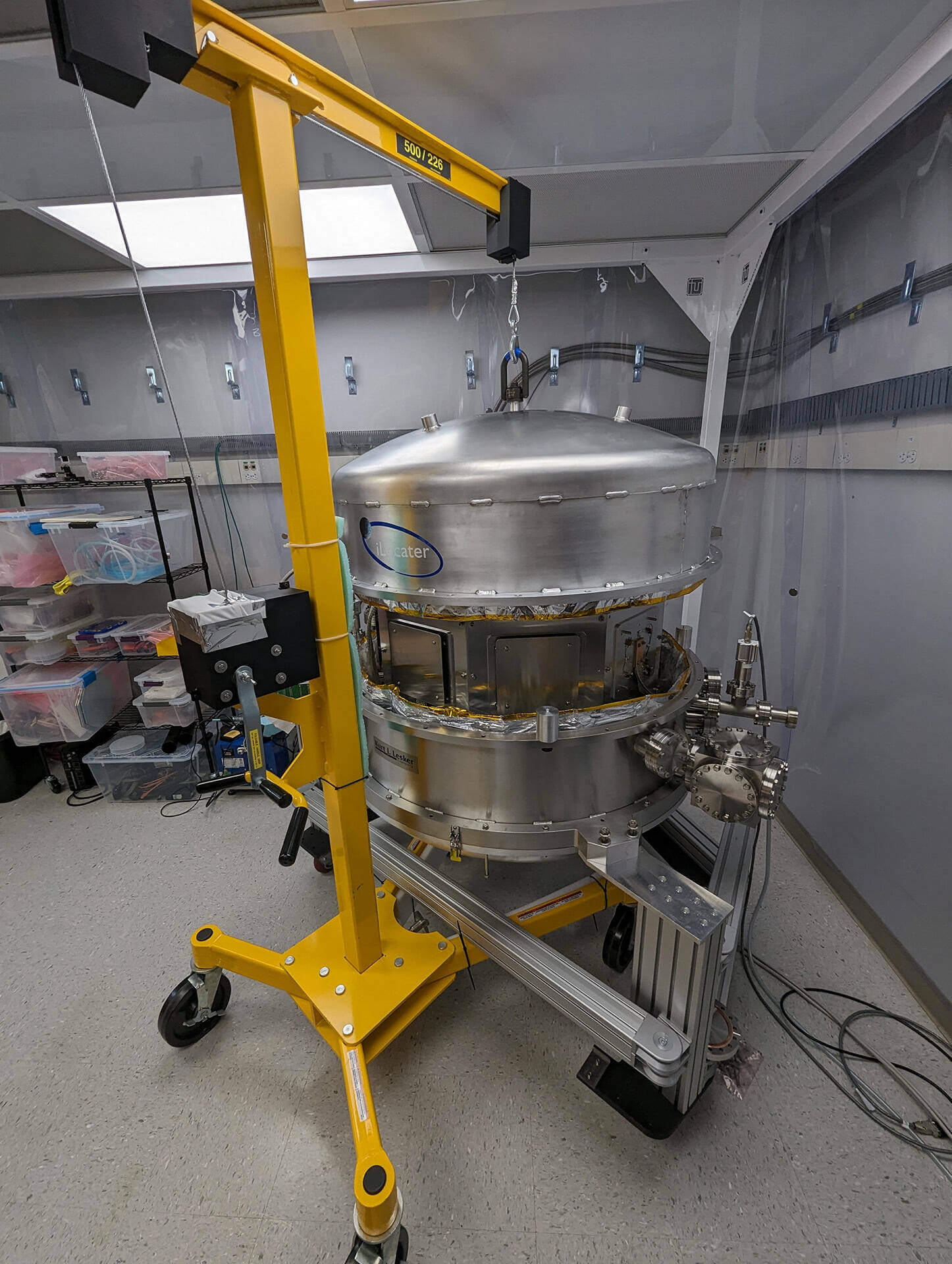
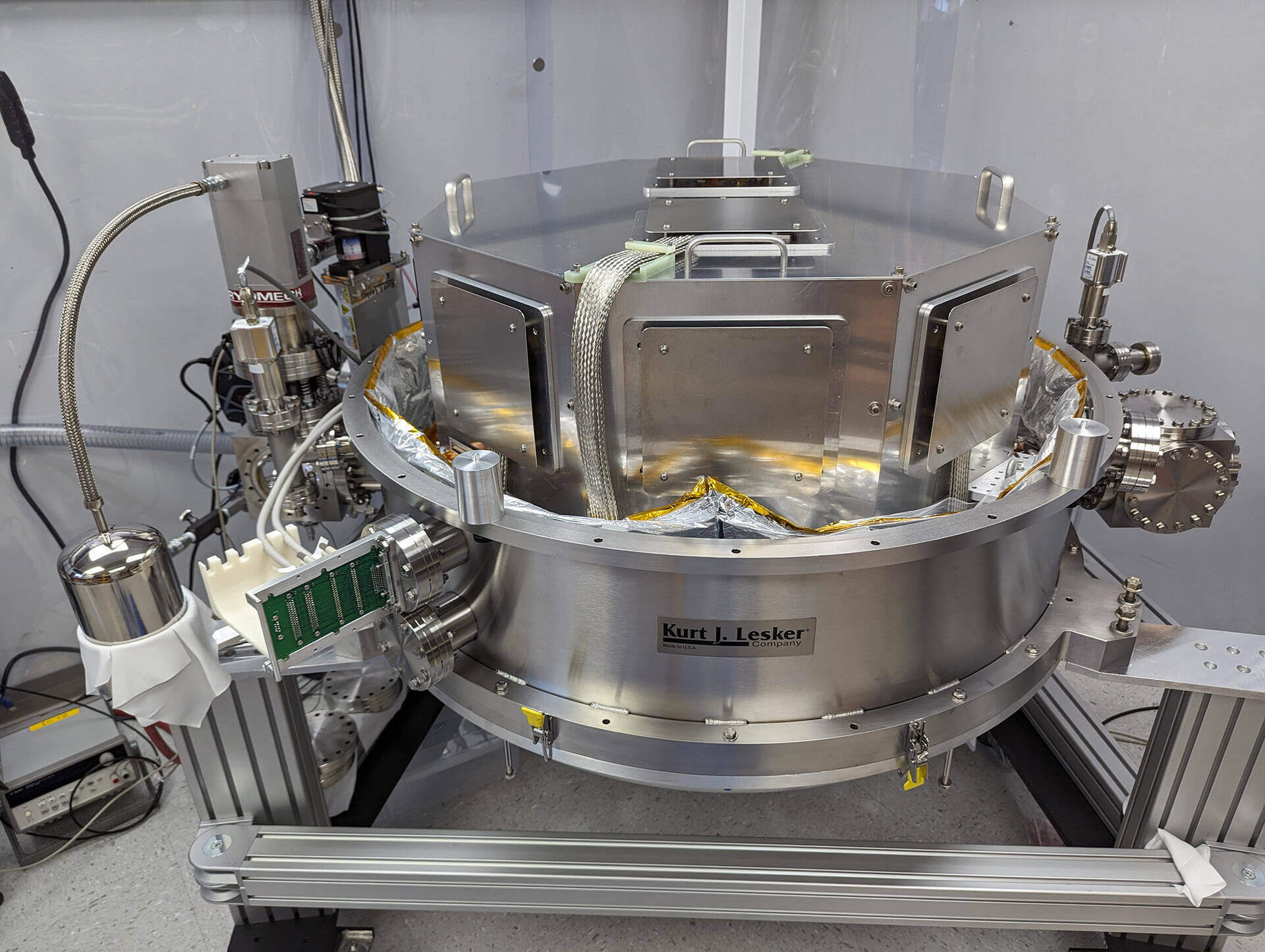
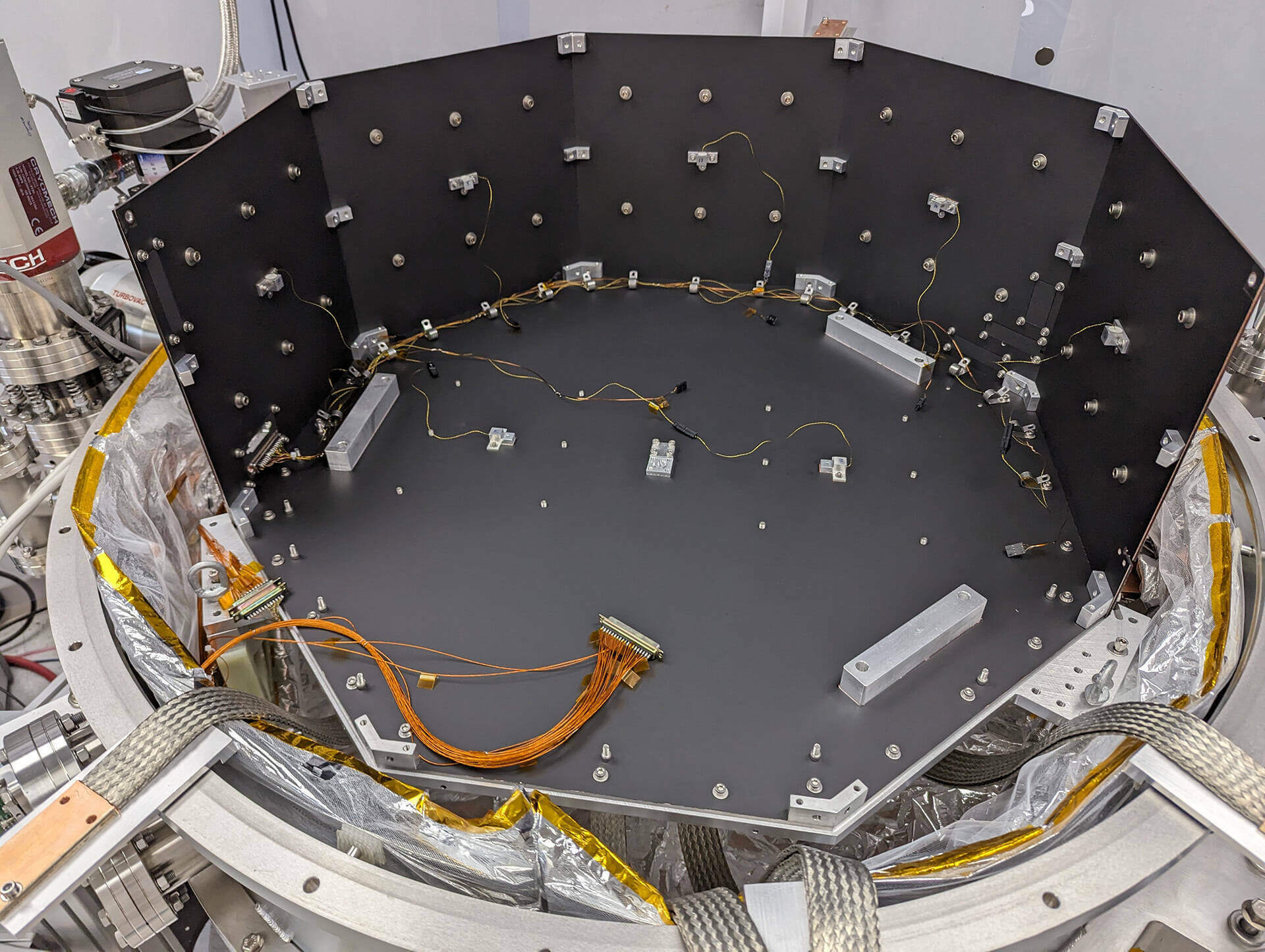
Cryostat
Achieving the stability levels required for EPRV science requires the spectrograph to be housed within a thermally stabilized vacuum environment. iLocater leverages the heritage of demonstrated thermal control systems implemented by the HPF and NEID spectrographs, where sub-mK stability has been routinely achieved on large instrument volumes. A change from the NEID and HPF design is the use of cryocoolers for cooling due to the instrument operating temperature, detector cutoff sensitivity and telescope constraints. Pulse-tube cryocoolers from Cryomech, optimized for vibration-sensitive applications, are used in combination with flexible copper thermal connections and isolation bellows to mitigate vibration impacts on the spectrograph. Full details of the cryostat can be found in Crass et al. 2022.
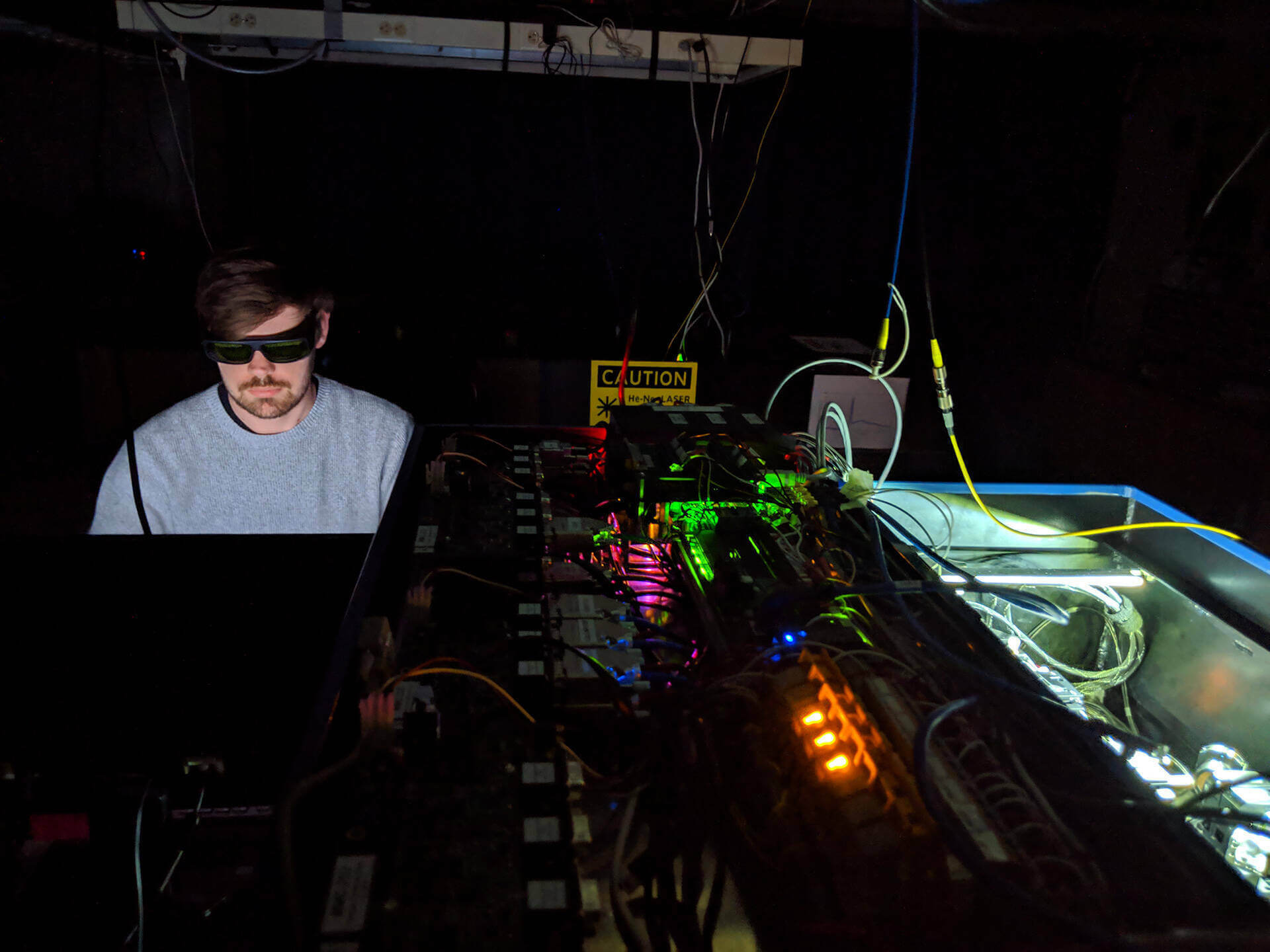
Wavelength Calibration System
The iLocater wavelength calibration system (WCS) uses a stabilized Fabry-Pérot etalon to generate a dense, periodic series of bright and stable peaks to calibrate the spectrograph. The etalon is illuminated using a supercontinuum source with a monitoring reference provided by an external alkali vapor (Rb) cell. The entire WCS is modular and was constructed by Prof. Christian Schwab at Macquarie University. SMFs are used to optically connect individual elements and make it well suited for illuminating an SMF-fed spectrograph. Stabilized etalons track instrument drifts at the level of 1 part in 1011 and demonstrate calibrator stability of ~3 cm/s when locked to the hyperfine transition lines of a Rb vapor cell. Several EPRV instruments currently use this technology including Maroon-X on Gemini North, NEID on WIYN and the Keck Planet Finder.